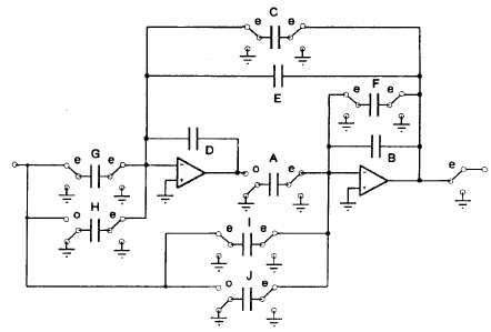
Fig. 5.3: SC filter circuit.
5.2. SC filter
This example also employs only structural description. The circuit shown in Fig. 5.3 contains switches, therefore the ideal switch, an Alecsis built-in component, is used. It should be noted that a truly ideal switch is used, with resistance zero for closed switch and infinite resistance for open switch [Ref.Mrča93] The parameters val_on and val_off determine voltages that turn switch on and off, respectively. There is another parameter hyst that defines switch with hysteresis if set on 1. The switch description requires four nodes: the first two are topological information of switch position in the circuit, and last two are controlling nodes. The double switch from Fig. 5.3 is described as a module named Double_Switch. It consists of two switches that charge and discharge capacitors making them behave as they were resistors.
Fig. 5.3: SC filter circuit.
module Double_Switch (even,odd,common,commutation) { // Declaration section
switch se,so; // Structural section
se (common,even,commutation,0) val_on=val_off=0;
so (common,odd,0,commutation) val_on=val_off=0;
}
The SC filter circuit is excited through a sample and hold circuit, shown in Fig 5.4.

Fig. 5.4: Sample and hold circuit
The sample/hold circuit is also described as a separate module SH_circuit, with three interface nodes.
switch se,so;
capacitor c1,c2;
opamp opamp1,opamp2;
se (input,sample,commutation,0) {val_on=val_off=0;}
c1 (sample,0) 1pF;
opamp1 (internal,sample,internal);
so (internal,hold,0,commutation) {val_on=val_off=0;}
c2 (hold,0) 1pF;
opamp2 (output,hold,output) ;
}
Switches are controlled by the voltage at the node called commutation. Its value, depending on weather it is greater or less than zero, determines state of the switches. Operational amplifiers are modeled as ideal (single voltage controlled source).
For the simulation, sine wave of frequency 128kHz is used to control the switches. In Fig. 5.5 simulation results are shown: excitation and response of the SC filter circuit.
Fig. 5.5: Simulation results for SC circuit excited by triangular input signal.